
7 Sheet Metal Design Tips to Reduce Manufacturing Costs
Time : Aug 27, 2026 View : 56
The best time to reduce sheet metal fabrication costs is before the drawing reaches the shop floor. Material waste, special tooling, welding, grinding, and rework often begin as design decisions. These seven sheet metal design tips help engineers remove those costs without compromising function.
Use them as a pre-RFQ review, then confirm the final dimensions with the fabricator’s machines, tooling, material data, and inspection plan.
Where Sheet Metal Fabrication Cost Starts
Most quotes reflect four connected cost groups: material, machine time, labor, and quality risk. A change that looks minor in CAD can affect more than one group.
| Design choice | Typical cost effect |
| Irregular flat pattern | More scrap and cutting travel |
| Short flange or inaccessible bend | Special tooling, extra setup, or secondary machining |
| Hole inside a bend zone | Distortion, rework, or a changed process sequence |
| Unnecessary welded parts | More fitting, welding, grinding, and inspection |
| Tight nonfunctional tolerance | Slower processing and higher rejection risk |
1. Design the Flat Pattern for Better Material Utilization
Start with the unfolded part, not only the finished 3D form. Simple outlines, shared straight edges, and efficient nesting reduce offcut waste and cutting travel. Avoid narrow projections unless they are functional; surrounding material may become scrap even when the feature is small.
For repeat production, review nesting before freezing the outline. Moving a tab or separating a small component from a large blank may improve sheet yield without changing the assembly.
2. Use the Lightest Practical Material and Gauge
Do not choose thickness by habit. Define the loads, stiffness, corrosion exposure, joining method, and finish, then select the minimum thickness that satisfies them. Thicker sheet also needs more cutting power, bend force, and handling.
Material grade matters too. Coated mild steel may cost less than stainless steel in a suitable environment, but corrosion behavior and finishing requirements change. Use the website’s sheet metal thickness selection guide as a starting point, then validate the choice for the application.
3. Standardize Bend Radii and Keep Flanges Tool Friendly
Repeated bend radii let the shop use fewer tool changes and make bend allowances easier to control. Very small inside radii increase cracking risk, while short flanges may not sit correctly across the lower die.
A production example shows the hidden cost. A 1.5 mm steel part specified a 4.2 mm hemmed edge. General purpose tooling could not form it directly, so the edge had to be made larger, hemmed, and milled back. One short dimension created an extra operation.
DFM Check: Can the Press Brake Reach Every Bend?
Check the full bend sequence. A formed wall can collide with the punch, die, or machine. Minimum flange and bend radius depend on material, thickness, die opening, punch geometry, and bend method. Review the deeper DFM guidance for sheet metal bending before release.
4. Keep Holes and Slots Away from Bend Zones
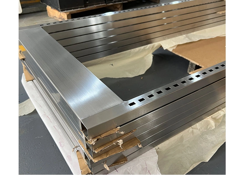
Holes too close to a bend can stretch, become oval, or tear. Correcting them may require secondary drilling or a looser tolerance.
A Practical Clearance Starting Point
The supplied guidance recommends keeping a slot edge at least the inside bend radius plus twice the sheet thickness from the bend edge. It recommends punched hole edge distances of one material thickness when the hole and outside edges are not parallel, and 1.5 times thickness when they are parallel. These are starting guidelines; tooling, alloy, temper, and hole shape can require more clearance.
Use bend reliefs where a bend ends at a corner or width transition. Rounded internal corners also protect tooling better than sharp notches; the knowledge base uses an internal radius of at least 0.5 times sheet thickness as a starting rule for punched notches.
5. Reduce Part Count, but Split Parts When Bending Becomes Impractical
Fewer parts mean fewer drawings, fasteners, alignment steps, and inspections. Tabs, formed stiffeners, and integral mounts can replace brackets when the result remains easy to cut and bend.
One Piece or a Small Assembly?
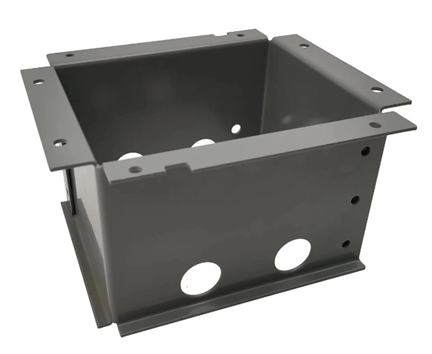
Do not force every assembly into one blank. A complex enclosure may create unreachable bends or tool collisions. Two simple formed parts joined by rivets, screws, or welds may cost less than one part needing special tooling. Compare bends, setups, hardware, weld length, finish access, and inspection.
6. Design Joints to Reduce Welding and Rework
Welding cost includes fixturing, fit-up, distortion control, grinding, cleaning, and inspection. Add locating tabs where appropriate, provide process access, and avoid a continuous cosmetic weld when a shorter or intermittent weld meets the engineering requirement.
Heat can pull an enclosure out of square. Balanced weld placement and sequencing can limit distortion, but sealing, strength, fatigue, and corrosion take priority.
See Deshibo Machinery’s custom sheet metal welding service for process options.
7. Apply Tight Tolerances and Premium Finishes Only Where Needed
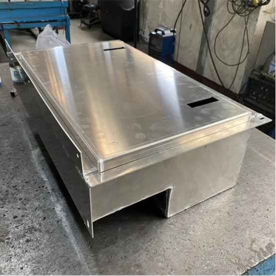
Every tight tolerance should protect fit, alignment, sealing, motion, safety, or appearance. Applying it to hidden, nonmating features raises inspection effort and rejection risk. Dimension from functional datums and avoid closed loops combining sheet thickness, bend variation, and hardware height.
Identify critical dimensions, burr direction, cosmetic surfaces, coating exclusions, and weld finish. State material grade, thickness, quantity, and revision. A complete RFQ supports an economical route and comparable quotes.
The OEM sheet metal fabrication cost guide explains other quote factors.
A Pre-RFQ Sheet Metal DFM Checklist
Before sending the drawing, verify that:
-
The flat patterns can nest without excessive scrap.
-
Material and thickness match the real load and environment.
-
Bend radii are consistent and every flange fits available tooling.
-
Holes, slots, and notches clear bend and edge deformation zones.
-
Part consolidation does not create an impossible bend sequence.
-
Joints are accessible and weld length is functionally justified.
-
Only functional features carry tight tolerances or premium finishes.
Lower Cost Starts Before the First Cut
Effective design for sheet metal fabrication balances performance and process simplicity. Review the flat pattern, bend sequence, clearances, assembly, and inspection as one system to cut cost without shifting risk into quality or delivery.
Deshibo Machinery can review your drawings against available cutting, bending, welding, and finishing processes. Send the material, thickness, quantity, drawings, and critical requirements to discuss a manufacturable, quote-ready design.
FAQ
Q: What design change reduces sheet metal fabrication cost the most?
There is no single change for every part. High scrap favors nesting changes; many setups favor standardized bends; heavy welding favors joint redesign; and high rejection risk favors clearer functional tolerances. Ask for a costed DFM review rather than assuming material price is the main issue.
Q: How far should a hole be from a sheet metal bend?
A useful starting point is an edge-to-bend distance of the inside bend radius plus twice the material thickness. It is not universal: hole geometry, alloy, temper, grain direction, tooling, and forming method may require more. Confirm the value with the fabricator.
Q: Is it cheaper to form one complex part or join several simple parts?
One formed part can remove hardware and labor, but only when every bend is accessible. Splitting the design can be cheaper when one piece causes press-brake collisions, special tooling, or machining. Compare material yield, bends, setups, fasteners, weld length, finish access, and inspection.
