
Sheet Metal Fabrication Tolerances: What OEM Buyers Need to Know
Time : Aug 28, 2026 View : 44
An OEM drawing may call out ±0.05 mm on several dimensions even though only two mounting holes actually control assembly. The fabricator can quote it, but maintaining those values after cutting, bending, welding, and finishing may require extra fixtures, inspection, machining, or rework. Cost rises quickly.
Good sheet metal fabrication tolerances are not simply “tight.” They are appropriate for the function of the part and realistic for the manufacturing process.
What Are Sheet Metal Fabrication Tolerances?
Sheet metal fabrication tolerances define how far a manufactured feature may vary from the nominal dimension shown on the drawing. A 100 mm width with a ±0.20 mm tolerance, for example, allows the finished part to measure between 99.80 mm and 100.20 mm.
That sounds simple. In practice, tolerances apply to more than overall dimensions. Buyers may need to control hole position, flange length, bend angle, flatness, perpendicularity, or the relationship between several features.
Not every feature deserves the same tolerance.
Typical Tolerances by Sheet Metal Fabrication Process
Tolerance capability changes as the part moves through production. A profile that leaves the laser cutter accurately does not necessarily keep the same dimensional condition after three bends and a welded bracket are added.
Laser Cutting Tolerances
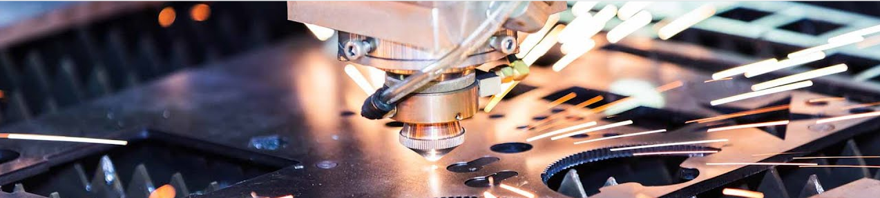
Laser cutting is generally well suited to accurate 2D profiles, holes, slots, and external contours.
Actual tolerance depends on material, thickness, geometry, machine condition, heat input, and feature size. Small holes in thick plate are a different problem from a large rectangular opening in 1 mm aluminum. A common mistake is to assume that every dimension shown on a laser-cut blank can be held equally tightly. Kerf behavior, piercing conditions, thermal effects, and narrow webs can make some features more sensitive than others.
Bending and Forming Tolerances
Bending adds variables that do not exist on a flat blank.
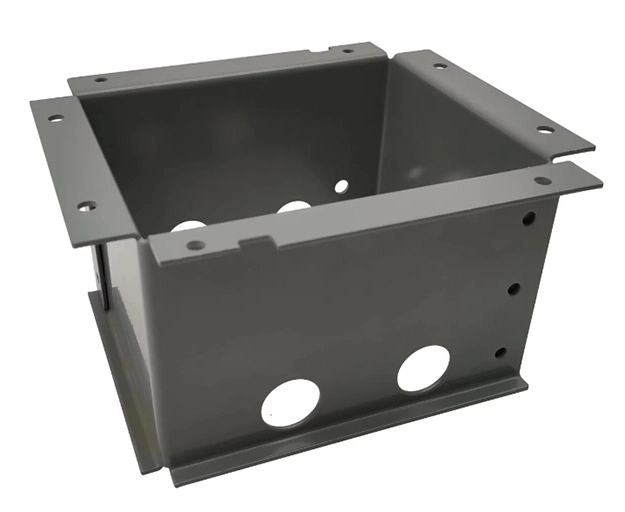
Material springback matters. So does grain direction, sheet thickness, bend radius, tooling condition, and the distance from a bend line to a nearby feature. Consider a small enclosure with four bends. Each individual bend may be acceptable, yet the finished width can still drift because dimensional variation accumulates from bend to bend.
This is tolerance stack-up in a very practical form.
Hole-to-bend dimensions deserve particular attention when those holes must align with another assembly.
Welding and Assembly Tolerances
Welding changes the part again.
Heat introduces shrinkage and distortion. Thin stainless steel panels can move noticeably during welding even when the cut components were accurate before assembly. Fixtures help. Welding sequence helps. Skilled operators help. None of them make thermal distortion disappear.
For a welded frame, the dimensions that matter most are usually the final assembly dimensions—not the dimensions of every loose component before welding. A supplier should understand that difference before production begins.
What Factors Affect Achievable Sheet Metal Tolerances?
Drawing tolerances cannot be evaluated in isolation. The same nominal requirement may be easy on one part and unnecessarily difficult on another.
Material Type and Thickness
Aluminum, stainless steel, and carbon steel do not behave identically during cutting and forming. Thickness variation also matters. A bend developed around nominal material thickness may shift slightly when actual sheet thickness changes within the mill specification. Springback is another source of variation, particularly on formed components.
Part Geometry
Geometry can make an apparently ordinary tolerance difficult.
Long narrow panels may distort. Small flanges can be difficult to form consistently. Holes placed very close to bend lines may deform. Large welded structures can pull out of square.
Parts with several bends deserve more attention because stack-up becomes significant. A drawing with twenty dimensions is not automatically difficult. A drawing with three poorly chosen critical dimensions can be.
Manufacturing Process
The process route matters as much as the individual machines.
A laser-cut plate may hold a feature location well while flat. After bending, that same feature is now controlled by the bend operation. After welding, heat distortion may influence it again.
When a feature truly requires tighter control, secondary CNC machining may be a better solution than forcing the entire fabrication process into an unrealistic tolerance window.
Equipment and Process Control
Modern CNC equipment improves repeatability, but equipment alone does not guarantee good parts. Programming, tooling, fixtures, bend compensation, welding sequence, inspection methods, and operator experience all affect the result.
The useful question is not whether a factory owns a laser cutter or press brake. It is whether the process is controlled from cutting through inspection.
Why Tighter Tolerances Can Increase Your Fabrication Cost
Tighter tolerances usually mean more control. More control may mean additional setup, slower processing, dedicated fixtures, extra inspection, lower production speed, or secondary machining. It can also increase scrap risk.
A typical example is a fabricated bracket with six holes. Two locate the bracket on an OEM machine. The other four simply accept bolts through oversized clearance holes.
Specifying the same tight positional tolerance on all six holes adds work without improving function. Critical-to-function dimensions should receive attention. Non-critical dimensions should have enough freedom for economical production.
How OEM Buyers Should Specify Tolerances on Their Drawings
A useful fabrication drawing tells the supplier where precision matters and where normal process variation is acceptable.
Identify Critical Dimensions
Mark dimensions that directly affect fit, alignment, sealing, motion, or assembly. Typical examples include mounting-hole patterns, mating surfaces, locating tabs, enclosure openings, and interfaces with purchased components. These are the dimensions a fabricator should protect throughout the process.
Avoid Over-Tolerancing Every Dimension
Blanket tight tolerances often create unnecessary cost. If a cover is attached with clearance holes, there may be no reason to control its overall width to the same level as a precision mounting pattern. Leaving reasonable manufacturing freedom on non-critical features often makes production faster and more stable.
Use Clear Datums and GD&T Where Necessary
When the relationship between features matters, datums and GD&T can make the drawing much clearer. Position, flatness, perpendicularity, and profile controls are useful when applied correctly.
Include Complete RFQ Information
A reliable quote needs more than a PDF drawing. Provide the 3D CAD file when available, material grade, sheet thickness, critical tolerances, surface finish, expected quantity, and inspection requirements.
If a dimension is especially important, say why.
How to Evaluate a Sheet Metal Supplier’s Tolerance Capability
Ask how critical dimensions are inspected. Ask whether welding distortion has been considered. Ask whether prototypes can be produced before volume manufacturing. For particularly demanding features, ask whether CNC machining can be added after fabrication.
Repeatability also matters. Producing one acceptable prototype is different from producing hundreds of assemblies that fit the same way.
A supplier that handles laser cutting, bending, welding, CNC machining, finishing, and inspection under a coordinated process has an advantage here. Fewer handoffs usually make tolerance discussions easier.
Work With Deshibo Machinery for Precision Sheet Metal Fabrication
Deshibo Machinery provides custom sheet metal fabrication for OEM applications, including laser cutting, CNC bending, welding, CNC machining, surface finishing, and assembly.
Tolerance requirements are best reviewed against the actual drawing, material, geometry, and production process. That is especially important for parts combining several fabrication operations.
Need help determining practical tolerances for your sheet metal parts?
Send your drawings to Deshibo Machinery for a manufacturing review and quotation.
FAQ — Sheet Metal Fabrication Tolerances
Q: What is a standard tolerance for sheet metal fabrication?
There is no single standard tolerance that suits every fabricated part. Practical values depend on material, thickness, geometry, and whether the dimension is checked.
Q: Is laser cutting more accurate than sheet metal bending?
For many 2D dimensions, laser cutting provides better repeatability than dimensions affected by bending.
Q: Why do tight tolerances make sheet metal parts more expensive?
They may require additional setup, inspection, fixtures, slower processing, tighter process control, secondary machining, or rework.
Q: What information should I send a sheet metal fabricator for an accurate quote?
Send 2D drawings, 3D CAD files when available, material grade, sheet thickness, required tolerances, surface finish, order quantity, and inspection requirements.
