
Sheet Metal K-Factor Explained: How to Calculate Flat Patterns
Time : Aug 07, 2026 View : 50
A flat pattern can look correct in CAD and still produce a flange that is 0.8 mm short.
During bending, the outside surface stretches and the inside surface compresses. Between them is the neutral axis, a layer that changes very little in length. Its location is not fixed at the center of the sheet. The K-factor describes where it sits and allows the bend region to be included in the blank length.
What Is the K-Factor in Sheet Metal Bending?
The K-factor is the ratio between the distance from the inside surface to the neutral axis and the total sheet thickness.
K = t ÷ T
Where t is the distance to the neutral axis and T is the sheet thickness.
A K-factor of 0.40 places the neutral axis at 40% of the thickness, measured from the inside surface. Material outside that line stretches. Material inside it compresses.
The K-factor is dimensionless. It is not bend allowance or bend deduction. Mixing these methods can produce a convincing but incorrect flat pattern.
Why Does the K-Factor Change the Flat Pattern Length?
The K-factor sets the neutral axis position. That position determines the arc length through the bend, which becomes the bend allowance.
A small change may only move one flange by a fraction of a millimeter. Add six bends and place holes close to the bend lines, and the error becomes visible.
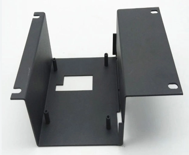
A common example is a U-shaped cover whose finished width is too narrow after two 90 degree bends. The real cause may be the unfolding rule, not the back gauge.
How Do You Use the K-Factor to Calculate Bend Allowance?
Bend allowance is the length of the neutral axis inside the bend zone. It is the material that must remain between the straight flange sections.
Bend Allowance Formula
BA = (π ÷ 180) × A × (R + K × T)
Where:
-
BA = bend allowance
-
A = bend angle
-
R = inside bend radius
-
K = K-factor
-
T = sheet thickness
The formula is simple. The inputs are not always simple. In air bending, the finished radius may not match the punch radius. Drawings also sometimes show the included angle rather than the angle through which the sheet is bent.
Simple Calculation Example
For a 2 mm sheet, 2 mm inside radius, 90 degree bend, and K-factor of 0.40:
BA = (π ÷ 180) × 90 × (2 + 0.40 × 2)
BA ≈ 4.40 mm
About 4.40 mm of material lies in the bend zone along the neutral axis. That result is useful only when the radius and K-factor match the real forming setup.
How Do You Calculate the Complete Sheet Metal Flat Pattern?
The method depends on how the flange dimensions are taken. This is where otherwise correct calculations often fail.
Method 1—Using Straight Flange Lengths and Bend Allowance
When flange dimensions run from the part edge to the bend tangent point:
Flat length = Flange 1 + Flange 2 + Bend allowance
For 40 mm and 30 mm straight flanges:
Flat length = 40 + 30 + 4.40 = 74.40 mm
Many drawings provide outside dimensions instead.
Method 2—Using Outside Dimensions and Bend Deduction
For outside dimensions:
OSSB = tan(A ÷ 2) × (R + T)
BD = 2 × OSSB − BA
Flat length = Outside flange 1 + Outside flange 2 − BD
OSSB is the outside setback. Bend deduction removes the overlap created when both outside dimensions extend through the bend area.
Do not mix tangent lengths with outside dimensions. The resulting blank can still look believable, which makes the mistake easy to miss.
What Factors Determine the Correct K-Factor?
No single K-factor works for every part.
| Factor | How It Can Affect the K-Factor |
| Material | Steel, stainless steel, and aluminum deform differently |
| Sheet thickness | Thickness changes strain distribution |
| Inside bend radius | Radius to thickness ratio moves the neutral axis |
| Bending method | Air bending, bottoming, and coining behave differently |
| Tooling | Punch radius and die opening affect the formed radius |
| Grain direction | Bending with or across the grain changes behavior |
| Material condition | Hardness and temper influence springback |
Published values are starting points, not production data. A 1.5 mm aluminum panel and a 3 mm stainless bracket rarely need the same value.
How Can You Find a More Accurate K-Factor for Production?
A test bend is usually more useful than another chart.
Cut a coupon from the same material and thickness as the production part. Record its flat length. Bend it with the intended punch, die, angle, and machine setup. Measure the finished flanges and inside radius, then calculate the actual bend allowance or bend deduction and work backward to the K-factor.
Save the result with the material grade, thickness, tool combination, and bend direction.
When Deshibo Machinery receives a model for laser cutting and CNC bending, one practical question is whether the customer’s flat pattern should be used or regenerated from finished geometry. For tight tolerance parts, finished geometry plus critical dimensions is often safer. The bend data can then be matched to the tooling used in production rather than to a generic CAD default.
What Are the Most Common K-Factor and Flat Pattern Mistakes?
Several errors appear repeatedly:
-
One K-factor is used for every material and thickness.
-
The punch radius is assumed to equal the finished radius.
-
Bend angle and included angle are confused.
-
Outside dimensions are mixed with tangent dimensions.
-
CAD applies bend deduction while a spreadsheet adds bend allowance again.
-
Hole positions are checked before bending but not after forming.
-
Springback is treated as a minor correction.
A test coupon catches many of these issues. A multi-bend prototype catches the interactions.
What Information Should You Send to a Sheet Metal Fabricator?
Send the 3D model, dimensioned drawing, material grade, thickness, bend angles, inside radii, critical tolerances, and surface requirements.
Mark hole to bend dimensions that cannot move. Note grain direction where it matters. Identify the dimensions that control assembly and the ones that can absorb normal forming variation.
For parts that will be laser cut, bent, welded, and finished by one supplier, share the assembly context. Deshibo Machinery can then review the blank against the bending sequence and welding fit up. A small adjustment—moving a slot 0.5 mm or adding bend relief—can prevent a full batch of awkward rework.
Conclusion: Use Calculations as a Starting Point and Test Data as the Standard
The K-factor connects material behavior, bend geometry, and flat length. Use formulas during design, then replace estimates with measured bend data. For tight tolerance parts, let the actual forming process define the value.
Before releasing a sheet metal design for production, ask the fabricator to review the bend parameters and confirm whether the submitted flat pattern matches the tooling that will be used.
FAQ
Q: What is a typical K-factor for sheet metal?
Values from about 0.30 to 0.50 are common starting points. The correct value depends on material, thickness, radius, tooling, and bending method.
Q: Is K-factor the same as bend allowance?
No. The K-factor locates the neutral axis. Bend allowance is the arc length of that axis through the bend.
Q: Can CAD software calculate the flat pattern automatically?
Yes, but the result is only as accurate as the K-factor, bend deduction, or bend table entered into the software.
Q: Should the fabricator use the customer’s flat pattern?
Not always. For critical parts, finished geometry may be safer because the fabricator can unfold it using verified shop data.
Q: Why are holes near bends often out of position?
The bend rule may be wrong, or the hole may sit inside the deformation zone. Springback and tooling variation can add more shift.
