

Sheet Metal Bend Relief: Width, Depth, and Corner Design
Time : Oct 16, 2026 View : 4
A sheet metal bend relief is a cut that lets a flange bend without pulling against neighboring material. To design it well, give the opening enough width for the material and cutting process, extend it beyond the bend zone, and check what remains after forming. A clean bend is only part of the job: the finished corner must still fit, support its load, and accommodate any seal or joint.
For brackets, trays, and equipment enclosures, we recommend reviewing reliefs in three states: the flat blank, the formed part, and the assembled product. Each reveals a different problem.

When Does a Sheet Metal Part Need Bend Relief?
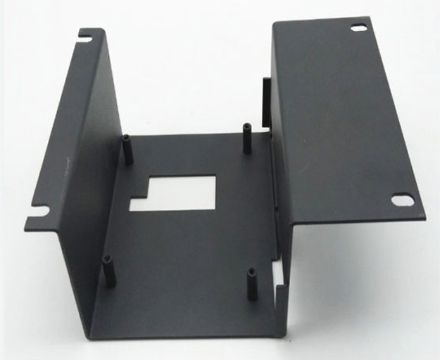
Relief becomes important where a bend stops but the surrounding sheet continues. Imagine a short flange folded upward from only part of a panel edge. Without separation at its ends, that flange drags the adjacent flat material into the bend. The result can be a torn edge, a bulge, or an unwanted twist.
Typical locations include partial flanges, stepped edges, and corners where adjacent bends meet. An unobstructed bend running across the full width of a blank may need no extra relief.
Treat laser cutting and bending as one connected design task. The cut defines which material can move independently; the bend determines whether that separation is sufficient.
How Should You Size Bend Relief Width and Depth?
Width and depth solve different problems. Dimension them separately instead of placing one ambiguous “relief size” note on the drawing.
Width is the clear distance across the slot, measured perpendicular to its length in the flat pattern. A useful initial layout is a width equal to or slightly greater than sheet thickness. Also check the cutting process: a narrow slot that looks acceptable in CAD may be difficult to cut consistently in the selected material.
Depth determines whether the slot clears the material that will deform. In the developed model, identify the bend zone between the tangent boundaries. The relief must extend beyond that zone into the adjoining flat region, with the additional clearance agreed for the forming process. State where the depth dimension starts and ends. A centerline, tangent line, and outside formed edge are different references.
Consider an illustrative width check. For 1.5 mm sheet, suppose the design uses a 1.8 mm slot with an agreed cutting tolerance of ±0.1 mm. Its minimum width is:
1.8 − 0.1 = 1.7 mm
That remains above the nominal sheet thickness. Next, check maximum permitted stock thickness and whether the chosen cutting process supports this opening. This arithmetic checks width only; it does not establish relief depth.
Keep nearby fasteners in the review. Adding a relief can leave too little metal beside a mounting hole, so check hole-to-bend clearance and the remaining ligament together.
Which Bend Relief Shape Fits the Part?
Choose the shape after locating the bend zone and identifying the material that must remain. Enlarging an opening until the CAD model unfolds can remove useful support around a mounting point.
|
Relief Form |
Useful Design Situation |
Main Check |
|---|---|---|
|
Rectangular slot |
A straight flange ends beside a flat panel |
The slot must clear the bend zone without leaving a narrow, weak strip. |
|
Round-ended slot |
A relief terminates within the sheet |
A rounded root softens the abrupt transition; adequate depth is still essential. |
|
Corner cutout |
Two or more flanges meet |
Review the opening after every bend and in the final assembly. |
A rounded end cannot compensate for a slot that stops too early. Likewise, a large corner opening may form easily while creating a difficult weld gap. Shape, size, and final function must agree.
How Do Corner Reliefs Affect Enclosure Assembly?
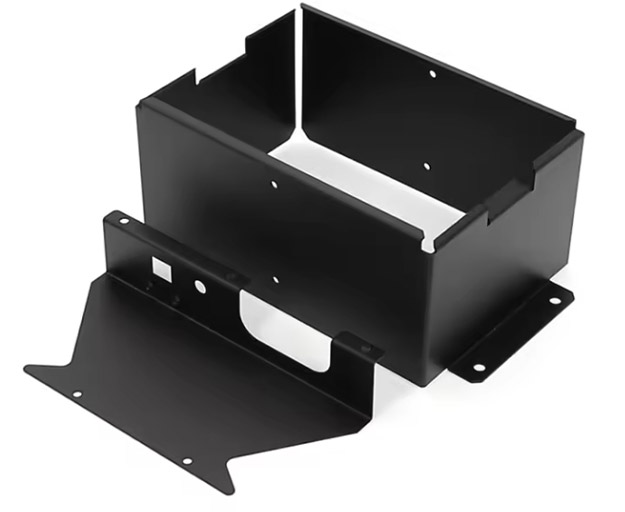
On an enclosure, the relief opening becomes part of the finished boundary. Check where it sits relative to a gasket, overlapping panel, mounting flange, or welded seam.
A cutout crossing the gasket contact path can interrupt sealing. A gap beside a loaded mounting point can reduce the material carrying that load. For welded sheet metal assemblies, the opening must also suit the intended joint and welding access. An oversized relief can increase the amount of material that must be bridged.
Review the bend sequence as well as the final model. A flange that clears its neighbor in the completed assembly may interfere while being formed. The remedy could be a different sequence, revised corner geometry, or a separate component—not simply a larger notch.
What Should You Check on a Bend Relief Prototype?
Inspect the first formed part before coating or cosmetic finishing makes small defects harder to see. We recommend recording these five checks against the drawing:
Relief root: Look for tearing or cracks where the cut ends.
Adjacent surface: Check for bulging, twisting, or material pulled out of plane.
Flange geometry: Measure angle and position from the defined datums.
Nearby features: Confirm holes, slots, and mounting surfaces retain their required geometry.
Assembly fit: Fit the mating panel or gasket and inspect the corner opening.
If a defect appears, identify its location before changing the relief. Cracking along the bend itself also calls for reviewing material condition and inside radius. Reproduce the intended bend sequence so the prototype evaluates the process that production will actually use.
FAQ
Does Every Bend Need a Relief Cut?
No. A full-width bend with free edges may form without additional cuts. Relief is most relevant where a moving flange remains connected to neighboring material, or where intersecting bends create corner interference.
Can a Round Hole Replace a Bend Relief Slot?
Sometimes, but it must free the required material throughout the bend zone. If a hole leaves a connecting bridge beside the flange, it may not provide the separation that an open slot would.
Will Bend Relief Prevent All Aluminum Cracking?
No. Relief addresses local restraint near the bend termination. Alloy, temper, rolling direction, edge condition, and inside bend radius still influence cracking. Review those factors if cracks extend along the bend rather than just its end.
Should Powder Coating Fill a Corner Relief Gap?
No. Powder coating is a surface finish, not a designed gap filler. Resolve corner closure through the part geometry, joint, or sealing arrangement, then verify the finished assembly against its intended protection requirements.
How Can You Complete Your Bend Relief Design Check?
Choose the most constrained corner in your design and trace it from flat pattern to formed part to assembly. Confirm width, depth references, remaining material, and closure before repeating the detail elsewhere. Then check the surrounding geometry against DFM for bending, especially tooling access and bend sequence. A relief is complete when the corner both forms cleanly and works in the product.
