
Hole-to-Edge and Hole-to-Bend Distance in Sheet Metal: DFM Minimums
Time : Sep 17, 2026 View : 0
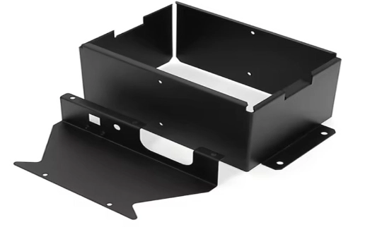
A hole can be correct in CAD and still fail on the brake press. A 6 mm round hole may return slightly oval or pulled toward the bend. Near a trimmed edge, too little material can roll or tear during assembly.
Two dimensions usually control the result: hole-to-edge distance and hole-to-bend distance. Both affect strength and dimensional stability. The values below are practical DFM starting points. Tooling and material behavior set the final limits.
What Is DFM in Sheet Metal Fabrication?
DFM means design for manufacturing. It matches the part to a process that can produce it consistently. Thickness and material grade matter. Hole geometry and bend radius matter as well. Tooling and tolerance do too.
A 1 mm aluminum prototype does not behave like a 4 mm stainless-steel bracket. Cutting heat and forming load differ. Early DFM review connects the drawing to the process route. Before ordering custom sheet metal fabrication, a small CAD change can prevent tooling changes or repeated inspection later.
Hole-to-Edge Distance in Sheet Metal
Edge clearance protects the strip between a hole and the outside profile. That material must survive processing and may also carry clamp load.
Definition
Hole-to-edge distance is normally measured from the hole center to the nearest outside edge. Some drawings show the remaining material from the hole wall instead. These are different dimensions.
For a round hole, the clear ligament equals the center-to-edge distance minus half the diameter. A 6 mm hole centered 9 mm from the edge leaves 6 mm of material. Mark the datum clearly, especially beside a radius or chamfer.
Practical Starting Guidelines
These values work as layout screening rules, not universal acceptance limits.
| Design condition | Starting guideline | Main concern |
| Round hole near a straight edge | At least 1-1.5 x hole diameter from hole center to edge | Edge breakout |
| Thin sheet or heavily loaded part | Consider 2 x material thickness or more | Strength and tearing |
| Slot near an edge | Leave more distance than for a round hole | Stress concentration |
| Small hole in thick material | Confirm with the fabricator | Heat and distortion |
Small ligaments can melt back under a laser or distort under a punch. The weakness may appear when a bolt is tightened and the tab curls inward. Slots need more room because their ends concentrate stress. Extra edge margin is usually cheaper than a later stiffener.
Hole-to-Bend Distance in Sheet Metal
Distance from a bend is less intuitive because the material moves. The outside stretches while the inside compresses.
Why Holes Near Bends Are Risky
A hole entering the bend zone can elongate as the flange rotates around the punch. Round holes become oval. Slots open at one end. Countersinks are less forgiving because their thin rim deforms easily.
This often happens on small mounting flanges. A fastener hole moves inward to save 3 mm of enclosure width. The blank cuts cleanly, but the press brake pulls the hole toward the bend. Assembly position is then out of tolerance. Moving the hole is the cleanest correction. A wider flange or bend relief may also work. Complex parts deserve a practical DFM for bending review before release.
Common Starting Formula
A useful preliminary rule is:
Hole-to-bend distance >= 2.5 x material thickness + inside bend radius
Use one measurement convention throughout the drawing. Here, distance runs from the nearest hole edge to the bend line. With 2 mm sheet and a 2 mm inside radius, the starting clearance is 7 mm.
Long slots and large openings usually need more margin. High-strength material may as well. If space is fixed, move the bend or widen the flange. Other options are adding relief or machining the feature after forming. Post-bend machining protects position accuracy but adds setup cost.
How Material, Thickness, and Process Change the Minimum
Mild steel is usually predictable in cutting and bending. Stainless steel springs back more. Aluminum is softer, so narrow ligaments mark or distort readily. Grade and temper still matter.
Thicker stock needs more clearance because its bend zone grows. Process choice changes the risk. Laser cutting offers flexible profiles with little tooling commitment. Punching suits repeat production but has tool-to-thickness limits. CNC machining can finish a critical hole after forming, at the cost of another setup. A supplier managing laser cutting and bending together can check the flat pattern against brake tooling before cutting.
DFM Example: Checking a Part Before Production
Consider a 2 mm mild-steel bracket with a 6 mm hole and a 2 mm inside bend radius. A 9 mm hole-center-to-edge target follows the 1.5-diameter guideline. It leaves a 6 mm ligament.
For the bend, 2.5 x 2 mm + 2 mm gives 7 mm from the hole edge to the bend line. This is a screening value, not approval. A slot or tight position tolerance needs another look. Show bend lines and hole centers on the 2D drawing. Include radii and datums.
Sheet Metal Hole Placement Checklist
-
State material grade and finished thickness.
-
Dimension the hole size and shape. Mark its center location.
-
State whether clearance starts at the center or hole edge.
-
Check every hole against the nearest outside edge and bend line.
-
Review slots and countersinks separately. Do the same for tapped holes and hardware features.
-
Confirm the inside bend radius and expected forming direction.
-
Check for process and assembly interference.
-
Mark only genuinely critical tolerances.
-
Submit the 2D drawing with the 3D CAD model.
When to Ask a Sheet Metal Manufacturer for DFM Review
Request a manufacturing review for short flanges or crowded holes. Multiple bends and tight true-position requirements also deserve attention. Do the same before a prototype enters volume production. Manual correction on five parts will not suit five thousand.
The review should confirm cutting method and bend sequence. It should identify relief needs and features better made after forming. If the design combines formed sheet with machined interfaces, coordinated CNC machining services can reduce datum conflicts.
Frequently Asked Questions
Q: What is the minimum hole-to-edge distance in sheet metal?
For early layout, use 1-1.5 times the hole diameter from its center to a straight edge. Then check the ligament against thickness and load.
Q: How far should a hole be from a bend line?
Start with 2.5 times material thickness plus the inside bend radius, measured from the nearest hole edge. Tooling may require more room.
Q: Can Deshibo Machinery review my CAD file before production?
Yes. Deshibo Machinery can review sheet metal drawings involving cutting or bending. This also covers welding and machining. Prototype and production requirements can be checked before quotation.
Conclusion
Good hole placement keeps flanges straight and fasteners seated. It also makes inspection repeatable. Layout minimums are useful. The final distance must match the material and bend radius. Tooling and load matter too.
Working on a hole close to an edge or bend? Send the 2D drawing and 3D CAD file to Deshibo Machinery for DFM review and quotation. A few millimeters adjusted before release can remove an entire secondary operation.
