
Top Sheet Metal Design Mistakes That Increase Manufacturing Cost
Time : Apr 24, 2026 View : 35
Every phase of sheet metal fabrication—from picking materials to putting together the final pieces—can either cut costs or throw money away based on your design decisions. Plenty of teams overlook how tiny mistakes in shapes, hole positions, or specs build up into longer machining times and extra fixes. You control expenses best by creating parts that match actual production skills and how materials act.
Common Design Oversights in Sheet Metal Fabrication
Before we get into particular slip-ups, keep in mind that the basic structure of thin-sheet parts needs to focus on production needs and traits. You also have to factor in the quantity of items you’re making. Put simply, each choice in your design should tie into how the part gets cut, folded, and joined in the factory.
Ignoring Material Selection and Thickness Requirements
Picking the wrong sheet metal type ranks as one of the biggest errors that push expenses higher. You might go for a tough alloy when basic mild steel works fine. This choice hikes up the price of raw stock and drags out cutting and folding tasks.
The ease of making sheet metal parts covers how simple or tough it is to punch, fold, and stretch them. Solid ease means you use less material, take fewer steps to process, build basic molds, extend tool life, and keep quality steady. If thicknesses differ a lot across parts, fitting them during welding or joining turns into a real headache. Plus, think about rust protection—putting plain carbon steel outside without treatment can slash the item’s useful life in half.
Deshibo Machinery gives advice on this through its engineering help: Our design group works with clients right from the idea stage and adds value by suggesting tweaks. That way, you fine-tune both durability and production fit before slicing any metal.
Overcomplicating Part Geometry
Fancy outlines shine in software models, yet they often clog up the shop floor. Basic cutting shapes speed up the job, shorten the path of the tool, and trim down waste. Tight angles demand tiny laser tips or special punches, which slow everything down.
Keeping shapes straightforward won’t hurt your design’s value—it cuts setup times, quickens folding runs, and lowers scrap piles. Deshibo Machinery’s metal laser cutting bending services show clearly how tuned shapes boost accuracy and ease tool strain.
Mistakes Related to Bending and Forming
Folding mistakes hide until pieces snap on the brake press. You avoid breaks by grasping bend curves and material grain upfront.
Not Accounting for Bend Radii and Allowances
As material folds, the outside stretches while the inside squeezes in the curve spot. For any thickness, a tinier inner curve *r* ramps up that pull and push. If the pull on the outer curve tops the material’s max strength, splits and snaps happen. Folks who forget to figure bend extra length wind up with pieces that miss the mark in fittings or need grinding afterward.
A right bend curve keeps sizes spot-on. Follow this tip: Set the inner curve at least as wide as the sheet’s thickness for mild steel, and go bigger for stiffer metals. Today’s shops like Deshibo Machinery run CNC folders that depend on exact bend details—if your plans skip those, accuracy drops fast.
Designing Without Considering Grain Direction
Overlooking grain flow looks small until splits show up in folds. When you punch and fold in one go to make a 90° angle, pick softer materials to dodge cracks at the corner. Line up folds with the grain for even stretching and nicer finishes. You also save cash by planning sheet layout early, which cuts down on bad batches during test folds.
Errors in Hole Placement and Cutout Design
Veteran designers still put holes wrong near edges or folds, which weakens spots and causes twists in shaping or joining.
Placing Holes Too Close to Edges or Bends
When you plan punched holes, leave enough space from edges and between holes to stop breaks. The shortest gap from hole edge to part outline depends on the part’s form and hole type. Holes too near a fold line stretch into eggs shapes after bending. Stick to minimum edge gaps—often 1.5 times the thickness—to hold strength and looks.
Using Nonstandard Hole Sizes or Shapes
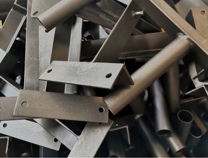
Custom hole forms might add style, but they call for unique tools. In tool building, round holes hold up best and prove simplest to cut and keep straight. Regular hole sizes smooth out punching and spare tool damage. Uniform holes across parts make lining up for rivets or bolts easier down the line.
Welding and Assembly Design Mistakes
Putting together problems stem more from bad spec planning or joint setups than from welder skills.
Overlooking Tolerances in Welded Assemblies
Specs rank high among things that shape quality and price. In making parts, pros know that despite spending time and cash, you rarely hit exact drawing sizes. Strict specs hinder lining up for welds; heat twists make fitting even harder. Small openings ease strain without harming weld strength.
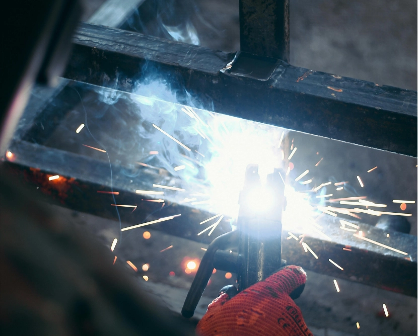
Deshibo Machinery’s metal welding service delivers steady outcomes with exact jigs built for repeat use—key for big runs of boxes or frames.
Failing to Plan for Ease of Assembly
Misaligned tabs or slots that don’t match grind assembly lines to a halt. Think modular: Craft pieces that snap together naturally. This cuts fix-up time.
Neglecting Manufacturing Capabilities During Design
Designers at times ignore that shops don’t have endless machines or tool choices.
Designing Without Considering Available Equipment Limits
Broad sheets beyond brake reach need outside help or splits—a pricey slip. Learn your supplier’s machine roster to skip this. Deshibo Machinery lists main tools like Bending Machine, Laser Cutting, CNC Stamping Punch, which set part size and feature bounds.
Team up with makers soon to dodge redesigns when pieces outgrow gear or need odd tools.
Ignoring Tolerance Stack-Up Across Multiple Processes
Tiny drifts from cutting to folding pile into big mismatches at the end join. Sync specs across steps to shrink those issues. Quick talks between engineers and makers cut expensive tweaks after test runs—a core DFM idea that many skip.
Strategies to Reduce Sheet Metal Fabrication Costs Through Better Design
Once you spot where costs sneak in, smart design tactics can flip those waste spots around.
Applying Design for Manufacturability (DFM) Principles
DFM goes beyond ideas; it links your goals to real workshop limits. Basic shapes fit current tools and trim switch times plus waste. Quick checks catch money pits like too many slots or snug curves before runs begin.
Learn how OEMs drop sheet metal fabrication costs with sharper designs, wise material picks, smooth joining, and exact output. This fits right with precision sheet metal fabrication aims—mixing function with easy making.
Collaborating with Precision Sheet Metal Fabrication Experts Like Deshibo Machinery
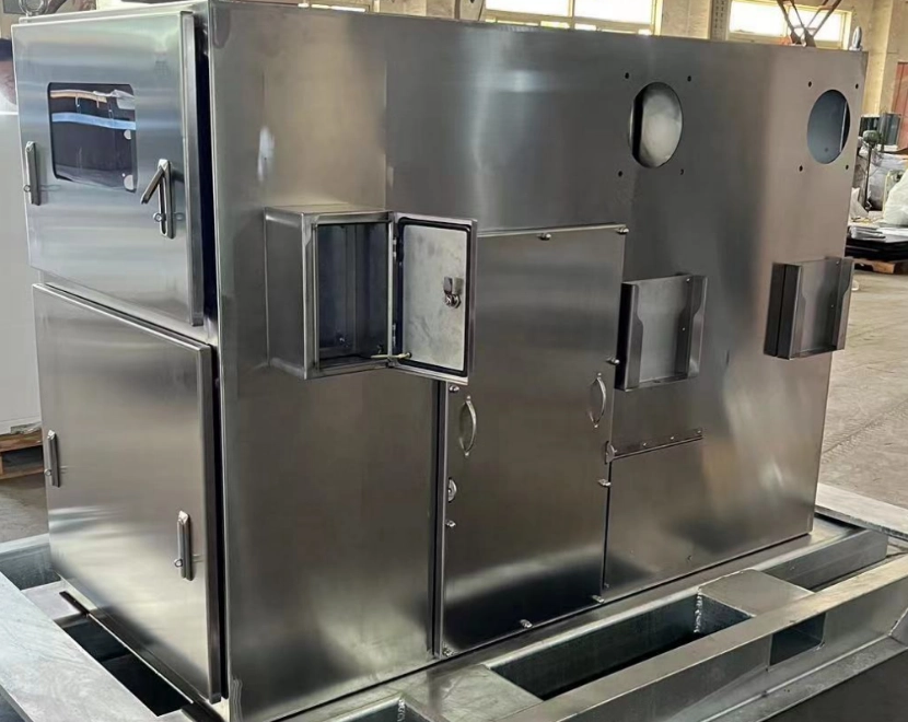
Teaming with skilled makers turns sketches into real items quicker. Deshibo Machinery shines by giving full from-start-to-finish metal fabrication options, including CNC machining, laser cutting, bending, welding, painting, anodize and powder-coating services.
We shift from ideas to finished goods smoothly, holding quality steady over all steps while keeping prices steady—a big win for OEMs wanting growth without losing detail.
Close work with such pros means less redoing, better material choices (from stainless steel to aluminum), and smoother finish flows—all vital when you compete worldwide on cost and trust.
FAQs
Q: What is the best way to reduce sheet metal fabrication costs?
Simplify part geometry, use standard hole sizes, choose appropriate materials, and apply DFM principles early in the design phase.
Q: How does grain direction affect bending quality?
Bending perpendicular to grain increases cracking risk; aligning bends along the grain allows smoother forming without fractures.
Q: What are common tolerance issues in welded assemblies?
Overly tight tolerances cause misalignment after heat distortion; allowing proper gaps improves weld consistency and reduces rework time.
Q: Which materials are most suitable for corrosion-resistant sheet metal parts?
Stainless steels like SUS304 or galvanized steels (SECC) offer excellent corrosion resistance while maintaining formability for complex shapes.
