
DFM for Bending: Top Sheet Metal Bending Mistakes to Avoid
Time : Apr 09, 2026 View : 24
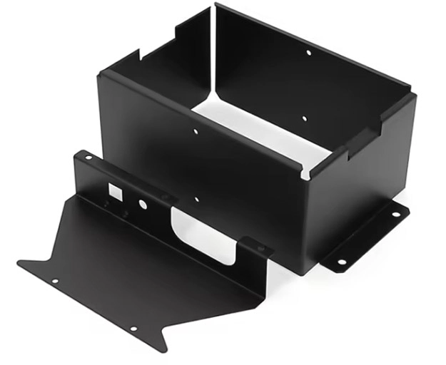
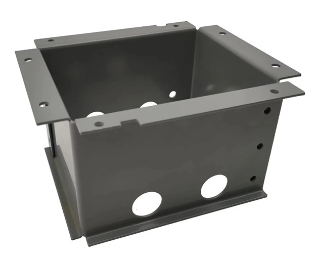
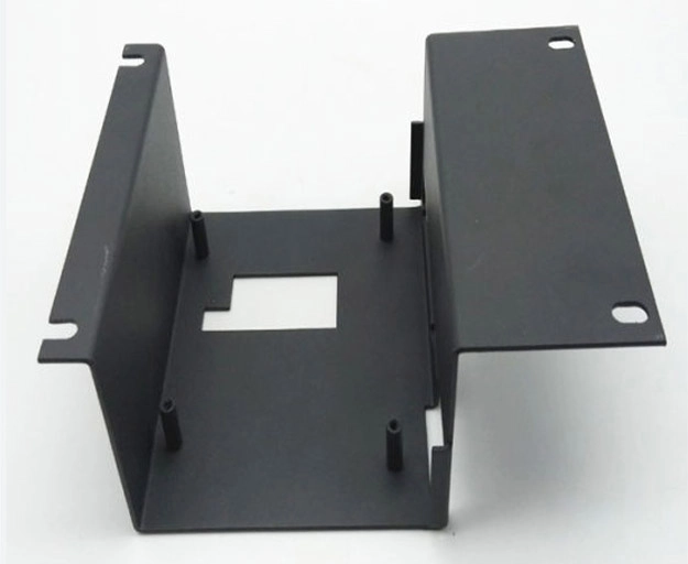
Bending sheet metal is relatively straightforward; it is the little design details that can cause problems down the line. Misjudging features such as bend locations, part-to-machine collisions and flange misalignment can cause unnecessary delays in production. These problems can be avoided if Design for Manufacturability (DFM) guidelines are adhered to by understanding how part geometry, tooling, and material properties interact to produce the finished component.
What DFM Means in Sheet Metal Bending
What does Design for Manufacturability (DFM) mean? DFM means that the part design was done with consideration to easy manufacturing. For sheet bending, this means that every bend in the part design can be accurately formed and safely manufactured within the limits of the available metal forming machines.
Integrating DFM into your sheet bending processes can save time and money by avoiding mistakes such as incorrect bend sequence or over-tight radii, excessive material stress, cracking or distortion. Well-designed bends provide consistent results across large quantities, and increase the tooling life cycle.
Avoiding Part-to-Machine Collisions During Bending
Before diving into specific design adjustments, it’s important to understand why collisions happen in the first place.
Common Causes of Collisions in Sheet Bending
Collisions typically occur when part geometry doesn’t match machine capabilities. Oversized flanges may hit the press brake frame or die during bending, especially if bend orientation isn’t optimized. Another frequent issue is insufficient clearance between bends — a problem often overlooked during CAD modeling.
How to Prevent Machine Interference
To avoid interference:
- Simulate the entire bending sequence using CAD software.
- Adjust flange length and orientation to ensure smooth tool movement.
- Communicate early with fabricators about press brake limits and tooling setups.
After cutting, thin sheets are typically subjected to further forming operations, such as bending. Consequently, it is important that the edge to be bent is perpendicular to the cut surface to prevent cracking where the cutting edge intersects the bend line.
Managing Corner Clearance and Bend Relief
Corner clearance is one of those small details that has a big impact on finished quality. Without proper reliefs, corners can tear or distort when bent.
Why Corner Clearance Matters in Bending Design
When two bends meet at a tight corner, material buildup increases internal stress. That not only weakens the corner but also causes dimensional inaccuracies in assemblies. When overlapping to create a 90° bend in a single process using punching, the material should not be too hard, otherwise it is prone to cracking at the right-angle bend. A process cut should be designed at the bend location to prevent cracking at the corner. This principle reinforces why bend reliefs are essential for maintaining structural integrity.
Designing Effective Bend Reliefs
Types of Bend Reliefs
- Rectangular reliefswork best for straight edges.
- Round reliefssuit curved or complex geometries where stress distributes unevenly.
Key Design Tips for Proper Reliefs
As a general rule the relief should be roughly equal to the thickness of the material plus the bend radius. It is also a good idea to try to keep the spacing between bends consistent so you avoid accidentally creating a fold where you don’t want it. These simple rules apply to every sheet metal fabrication project.
Preventing Distortion in Sheet Metal Bends
Even with perfect tooling, distortion can still occur due to uneven stresses during forming.
Factors That Lead to Distortion During Bending
Uneven material thickness, grain direction, or excessive forming pressure can all cause warping. Steep bends require specialized tools and are costly. Furthermore, excessively small bend radii can easily cause cracks and wrinkles on the inner surface. This shows how selecting an appropriate bend radius helps reduce deformation risk while keeping costs reasonable.
Techniques for Reducing Distortion
- Use recommended bend radii based on material type.
- Apply symmetrical bends whenever possible.
- Confirm flat pattern dimensions include accurate bend allowances before cutting begins.
These steps balance internal stresses so parts stay flat and true after forming.
Aligning Flanges and Parts Correctly
Accurate flange alignment ensures that assembled components fit perfectly without forcing or gaps.
The Role of Flange Alignment in Fabrication Accuracy
Misaligned flanges create visible defects and assembly challenges. Even minor angular errors multiply when multiple bends are involved, leading to tolerance stack-up issues across welded structures.
Tips for Maintaining Alignment During Design and Production
Designers can maintain precision by:
- Adding alignment holes or tabs for reference during setup.
- Checking flange lengths against minimum distance requirements.
- Using 3D visualization tools to confirm post-bend geometry before manufacturing starts.
To ensure accurate positioning of the blank in the mold and prevent blank misalignment during bending, resulting in defective products, process positioning holes should be added in advance during the design phase. This method ensures repeatable accuracy across multiple production runs.
Understanding Minimum Flange Length Requirements
Flange length plays a critical role in whether a bend can be properly formed on available equipment.
What Defines a Short Flange in Sheet Metal Bending
A short flange—one shorter than the minimum required by tooling—cannot be clamped securely during bending. It may slip under pressure, resulting in inaccurate angles or even tool damage. The height of the straight edge of the bend should not be too small; otherwise, it will be difficult to generate sufficient bending moment, making it difficult to obtain parts with accurate shapes. Its value h ≥ R + 2t is acceptable.
|
Material Type |
Recommended Minimum Flange Height (h) |
Notes |
|
Mild Steel |
h ≥ R + 2t |
Standard condition |
|
Aluminum Alloy |
h ≥ R + 1.5t |
Softer material allows shorter flange |
|
Stainless Steel |
h ≥ R + 2.5t |
Requires stronger clamping |
Designing Around Minimum Bend Requirements
Calculate minimum flange lengths considering punch radius, die width, and material thickness. If your design falls below this threshold, modify it slightly rather than forcing an unsafe operation.
Extend short flanges marginally or merge them into larger ones through redesign. These small tweaks make bending simpler while maintaining functional performance—a core DFM approach that saves time downstream.
Achieving DFM Success in Sheet Metal Projects with Proper Planning
Every successful fabrication project starts long before the first piece of metal is cut. Integrating DFM early eliminates surprises later on.
Integrating DFM Principles from Design to Fabrication
Review part geometry early with your fabrication team to identify potential issues before production begins. Good manufacturing processes should ensure low material consumption, few process steps, simple mold structure, long service life, and stable product quality. Working closely with partners like Deshibo can provide valuable feedback on manufacturability before committing to full-scale runs.
Deshibo’s expertise in custom sheet metal fabrication—including CNC machining, laser cutting, bending, and welding—makes it easier for engineers to turn precise digital designs into high-quality physical parts efficiently and affordably.
Benefits of Applying DFM Best Practices
Applying these principles consistently leads to:
- Shorter lead times through fewer revisions.
- Consistent quality across large batches of laser cut sheet metal components.
- Lower overall production costs thanks to reduced waste and rework cycles.
FAQs
Q1: What is the ideal bend radius for stainless steel sheets?
It depends on thickness; generally use an inner radius equal to at least 1×–1.5× the material thickness for stainless steel.
Q2: How do I prevent cracking at sharp corners during bending?
Add corner reliefs with radii no smaller than half the material thickness and avoid overly tight bends near edges.
Q3: Can simulation software predict part-to-machine collisions?
Yes, most modern CAD/CAM systems include press brake simulation features that flag potential collisions automatically.
Q4: Why does my bent part spring back after forming?
Springback occurs because of elastic recovery; adjusting tooling angles or adding stiffening ribs helps minimize it.
Q5: What factors influence minimum flange length requirements?
Tooling geometry (punch tip radius), die opening width, and material thickness collectively determine safe minimum flange lengths during sheet bending operations.
